Alpaca High Level Design
Alpaca is the code name for the computing and networking fabric deployed at data centers. Alpaca provides computing, storage, and network capabilities for the network's customers. The primary purpose is to provide services operated and maintained by the Network Operations Center. Some examples of services that run on Alpaca are Horizon, which offers desktop services for end users; Active Directory, which provides identity and authorization management; and Exchange, which offers email services. In the following section, we will break down the components of Alpaca and how they work together to deliver the capabilities required for the mission.
1.0 Network Infrastructure
Alpaca provides each server with 200 Gbps for Area Processing Centers (APC) or 400 Gbps for Regional Datacenters (RDC). This bandwidth is primary for the Software Defined Storage (SDS), which we will discuss later.
Each server connects to the Datacenter Core (DC-COR) switches. The DC-COR provides connectivity to the virtual hosts and uplinks to the Datacenter Service (DC-SRV) switches and Access Nodes (ANs) located within the site. Figure 1 below depicts the connectivity between a virtual host, the DC-CORs, and the DC-SRVs.
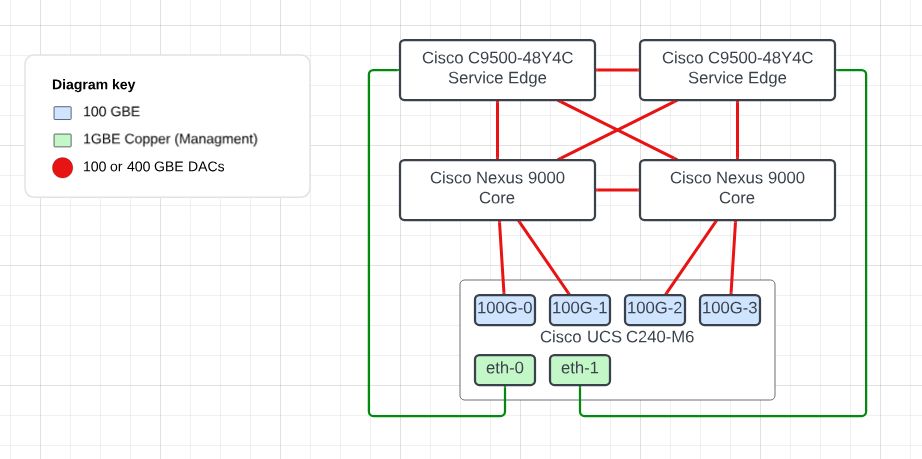
Figure 1 does not depict the connectivity of an AN. The AN would have a uplink to each DC-COR.
1.1 Datacenter Cores (DC-CORs)
Currently in RDCs we are utilziing the Cisco Nexus 9332D-GX2B see Figure 2 below and in the APCs we are utilizng the Cisco Nexus 9336C-FX2 see Figure 3 Below.
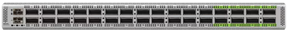
In Figure 2 Above The Cisco Nexus 9332D-GX2B is a compact form-factor 1-Rack-Unit (1RU) switch that supports 25.6 Tbps of bandwidth and 4.17 bpps across 32 fixed 400G QSFP-DD ports and two fixed 1/10G SFP+ ports (Figure 3). QSFP-DD ports also support native 200G (QSFP56), 100G (QSFP28) and 40G (QSFP+). Each port can also support 4x10G, 4x25G, 4x50G, 4x100G, and 2x200G breakouts. The last eight ports, marked in green, are capable of wire-rate MACsec encryption.
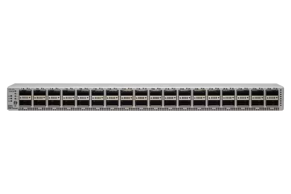
In Figure 3 above The Cisco Nexus 9336C-FX2 Switch is a 1RU switch that supports 7.2 Tbps of bandwidth and over 2.4 bpps. The switch can be configured to work as 1/10/25/40/50/100-Gbps offering flexible options in a compact form factor. Breakout is supported on all ports.
1.2 Datacenter Service Switches (DC-SRV)
Within Alpaca, we utilize the Cisco Catalyst 9500 Series switch. The specific model deployed across the network for DC-SRVs is the C9500-48Y4C switch. Figure 4 below provides a photo of the devices front view.

This device provides 48 ports of 1/10/25 GbE and 4 40/100 GbE ports for uplinks to the DC-CORs. The primary purpose of this device is to connect services within the datacenter. One example is th KGs that are used to connect to the other sites.
For more specifics on the devices capability please see the Cisco Catalyst 9500 Series Switch Datasheet
2.0 Protocols
It is essential to understand the various protocols and roles used within the network fabric. This section will provide you with a comprehensive overview of the topic.
2.1 Forward Error Correction (FEC)
FEC is a crucial technique used in data communication, including the network infrastructure within Alpaca. FEC is responsible for enhanced data reliability. FEC enables the receiver to detect and correct errors in data packets received without requesting the sender to resend them. This capability is precious in high-speed networks where retransmissions could significantly impact performance.
Configuring FEC on Cisco Nexus switches is essential for the proper operation of interfaces. The FEC mode determines how error correction is handled for the data passing through these interfaces. Not configuring FEC correctly or at all can result in interfaces not coming up, leading to connectivity issues within our network.
The following command configures Reed-Solomon FEC on the interface. Reed-Solomon FEC is a popular choice for error correction in optical communication systems, including those found in data centers, due to its efficiency in correcting burst errors and its ability to recover from multiple-bit errors in data packets.
For more information on the implementation of FEC in Cisco Optiocs please see the reference Cisco FEC PDF
The following provides an example configuration of an interface on a switch running Cisco NX-OS.
Note
fec rs-fec command is utilizing cl91 for the FEC mode.
The following provides an example configuration of an interface on a switch running Cisco IOS-XE.
Note
Remember to set the FEC on both ends of the link.
2.2 Open Shortest Path First (OSPF)
OSPF is a widely utilized Interior Gateway Protocol (IGP) designed for routing IP packets solely within a single routing domain, such as an Autonomous System. It is characterized by its speed and efficiency in finding the shortest path between nodes in a network, leveraging Edsger Dijkstra's algorithm for this purpose. RFC 2328 details OSPF for use in IPv4 networks, while RFC 5340 details it for IPv6. OSPF offers robust features, including support for multi-area configurations and various network links, such as point-to-point links, which we'll discuss in detail.
2.2.1 Basics of OSPF
OSPF operates on the principle of dividing the entire autonomous system into various areas to optimize network traffic and scalability. It uses Link State Advertisements (LSAs) to construct a network topology map. Each router in the OSPF network calculates the shortest path tree for itself using this topology database. Dijkstra's algorithm performs the shortest path calculation, allowing OSPF to adjust to network changes and reroute traffic efficiently and dynamically.
2.2.2 Multi-Area OSPF
OSPF allows the segmenting of a large autonomous system into smaller areas to enhance scalability and manageability. This hierarchical routing approach reduces routing table entries on individual routers and decreases the protocol's overhead. The following will touch on the backbone area and non-backbone areas:
- Area 0 (Backbone Area): In OSPF, Area 0 acts as the backbone to which all other areas must connect, directly or through virtual links. It facilitates the flow of routing information between non-backbone areas.
Note
We do not utilize virtual links in Alpaca
- Non-Backbone Areas: These are areas that are not Area 0. They can only communicate with each other through Area 0, ensuring a loop-free topology.