WolfPack requires the following Software to complete the installation:
VMware ESXi 8
Cisco Secure Firewall Threat Defense Virtual (7.4.1 or Higher)
Palo Alto VM Series (11.1.2-h3 or Higher)
Catalyst 8000V Edge Software (17.13.1a or Higher)
PowerShell 7 (latest Version)
PowerShell Modules:
VMware.PowerCLI
GooseSuite
Cisco.IMC
psyml
Info
For the remainder of the guide you will need to use your sites NAAS-001v Server. This server should have Powershell 7 and the required modules pre-installed.
The Palo Alto firewall requires access to the internet. Please ensure that v998.eXX-net-mgt subnet is included in the allow-nat access list of your sites PE.
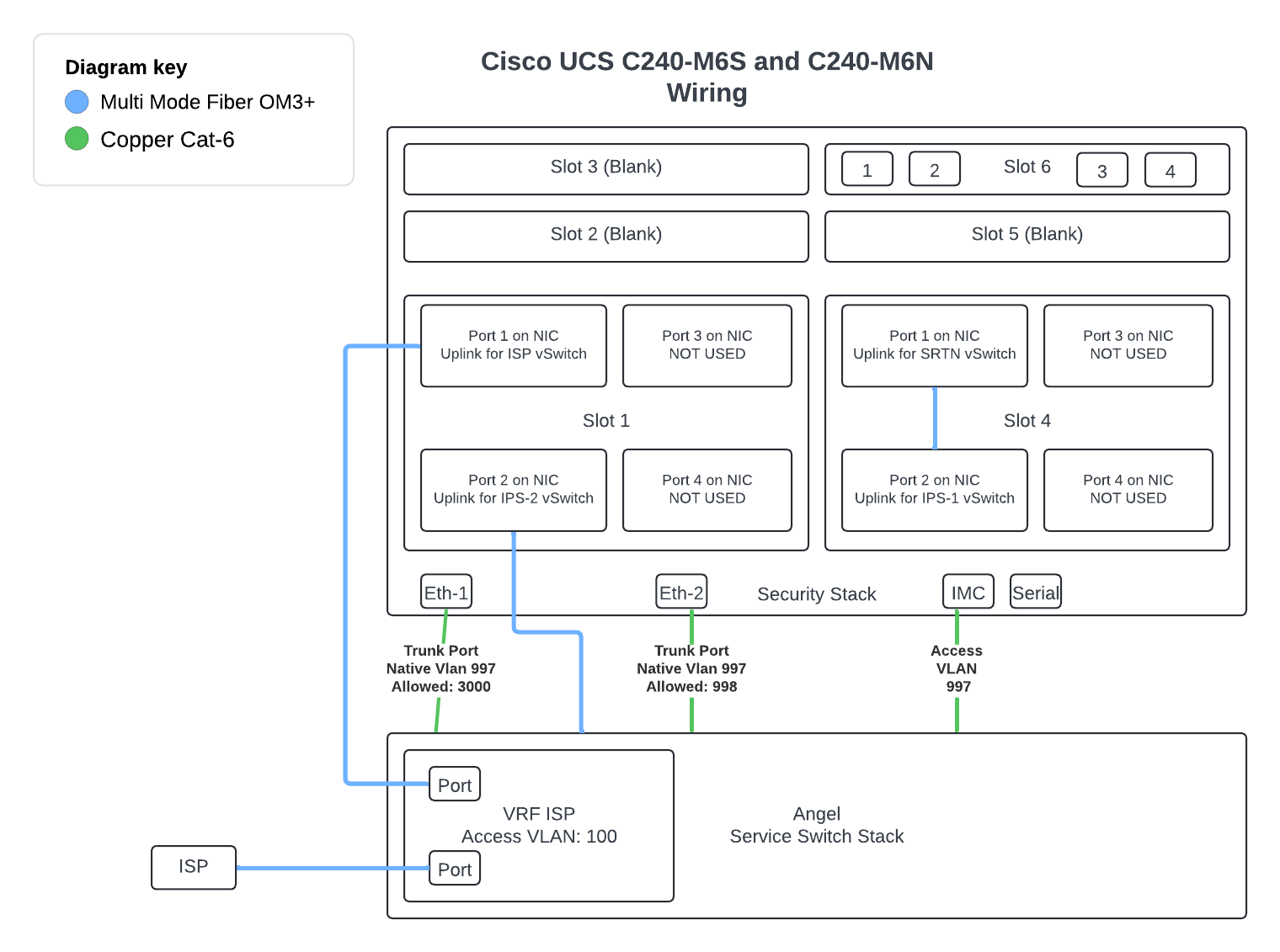
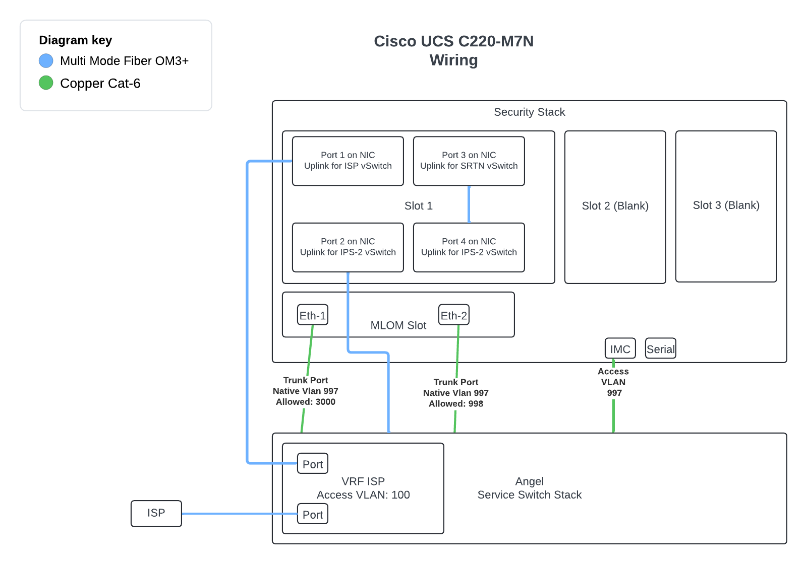
When you recieve your Security Stack Server, you will need to unbox the unit. Check to make sure you have power cables for the device. Verify your ISP media handoff (Single Mode Fiber / Multimode Fiber / Copper, etc). Make sure you have the correct SFP for the handoff.
2.1 Connect your Security Stack to Network Infrastructure
Next we will connect to the service switch. Please reference Section 1.4
Warning
If you do not have Service Switches you will only need to connect the copper ports for provisioning.
We will touch on what will be needed for loopback testing later on in this guide if you dont have service switches.
Find open ports on your service switch stack or other switch if you dont have service switches, and connect your ports with the the only exception being in the warning box above.
This is the connection to onboard port 2 for the M6 series and port 2 in the MLOM slot on the M7 series. This will provide connectivity for the oobm interfaces on the virtual network devices.
conf t
 interface twe X/0/X
  description UPLINK TO SS oobm vSwitch
  switchport
  switchport mode trunk
  switchport trunk native vlan 997
  switchport trunk allowed vlan 998
This is the connection to onboard port 1 for the M6 series and port 1 in the MLOM slot on the M7 series. This will provide connectivity for VMware management.
conf t
 interface twe X/0/X
  description UPLINK TO SS vSwitch0 vSwitch
  switchport
  switchport mode trunk
  switchport trunk native vlan 997
  switchport trunk allowed vlan 3000
For the ESXI install, we will be installing it manually. NetOPS has written a SOP for how to insteall the ESXI manually once you have the Security Stack cabled up.
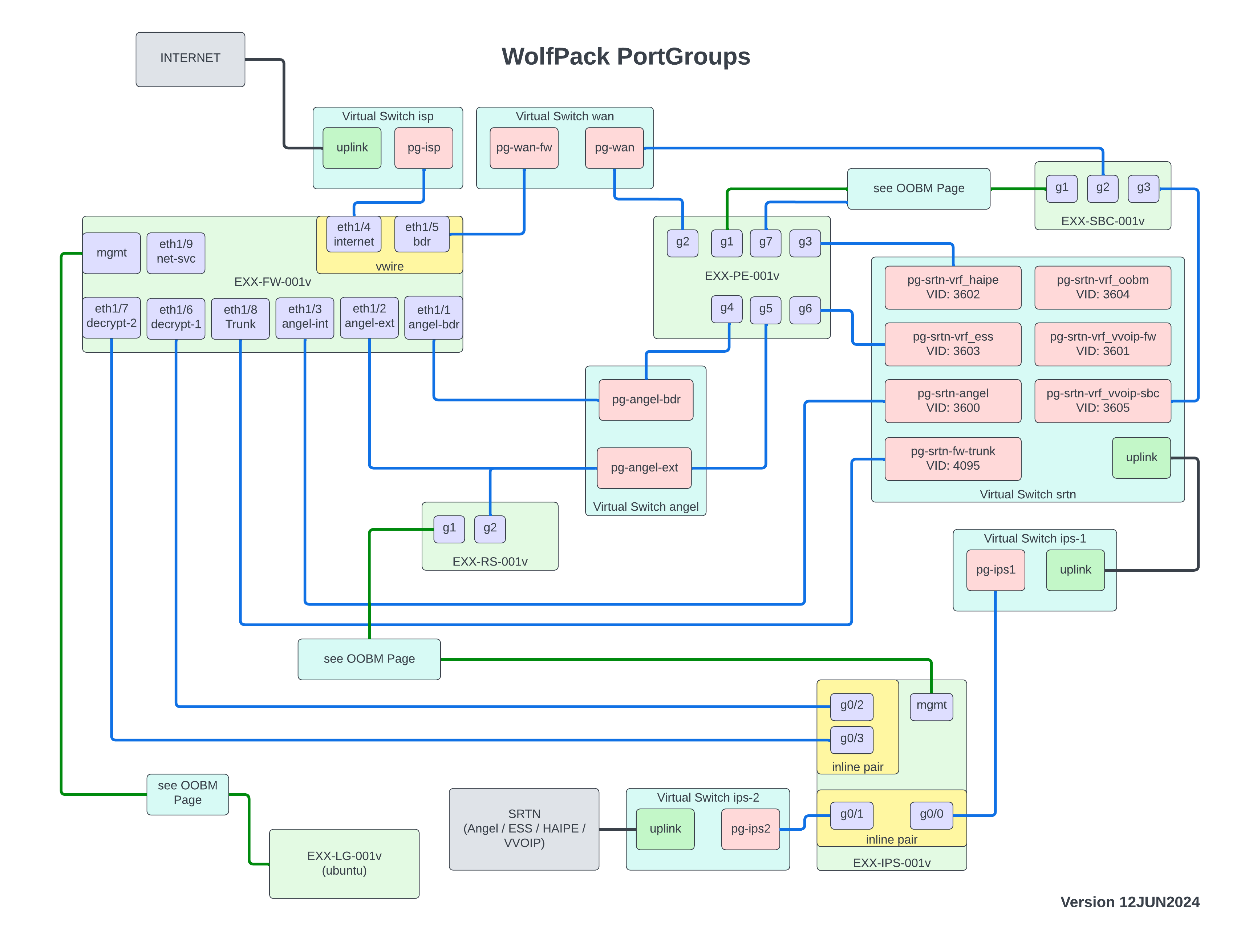
Below is the diagram that depicts the vSwitches and associated port groups required to support Wolfpack. These vSwitches are virtual standard switches and NOT virtual distributed switches.
# Update with the Security Stack vSphere Host IP or FQDN$serverName="Security Stacks' vSphere Host IP or FQDN"# Update to Site number$site="EXX"# 8000v OVF Path (Update as version changed)$cisco8000vOVFPath='\\angel.net\software\01 Third Party\Cisco\Device Software\C8000v\17.13.01a\c8000v-universalk9_vga.17.13.01a.ovf'# 8000v OVA Path (Update as version changed)$cisco8000vOVAPath='\\angel.net\software\01 Third Party\Cisco\Device Software\C8000v\17.13.01a\c8000v-universalk9.17.13.01a.ova'# Palo Alto OVF (Update as version changed)$paloAltoVMFwOVF='\\angel.net\software\20 Fabrics\WolfPack\Palo Alto\11.1.0\PA-VM-ESX-11.1.0.ovf'# Cisco IPS OVF (Update as version changed)$ciscoSftdvOvf='\\angel.net\Software\20 Fabrics\WolfPack\Cisco\SFTDv\7.4.1-172\Cisco_Secure_Firewall_Threat_Defense_Virtual-VI-7.4.1-172.ovf'#region Do not edit$vCentercreds=Get-Credential-Username"$ENV:USERNAME@angel.net"$securityStackHostCredentials=Get-Credential-UserNameroot-Message"Enter the Security Stack Root Password"# Connect to the vCenter or ESXi hostConnect-VIServer-Server$serverName-Credential$securityStackHostCredentials-Force#endregion Do not edit
Once the document is edited, open Powershell 7 and paste the entire script into powershell. Hit enter to run the script. The script will make your username your "ADF" username (as shown in Powershell) and will ask for a password. Enter one. It will then ask for a "root" password. Use the root password from your ESXI install.
On your local NAAS-001v server execute the following code. The following code block provides the necessary PowerCLI code to create vSwitches.
Note
No Editing is required in the following script
# Get the ESXi host object$vmwareHost=Get-VMHost-Name$serverName$virtualSwitches=@("angel","wan","ips-1","ips-2","srtn","isp","oobm")$numPorts=128$mtu=9000foreach($virtualSwitchin$virtualSwitches){$vmwareHost|New-VirtualSwitch-Name$virtualSwitch-NumPorts$numPorts-Mtu$mtu}
On your local NAAS-001v server execute the following code. The following code block provides the necessary PowerCLI code to create port groups on associated vSwitches.
# Get the ESXi host object$vmwareHost=Get-VMHost-Name$serverName$portGroups=@(@{switch="isp"name="pg-isp"vid="0"promiscuousMode=$truemacAddressChanges=$trueforgedTransmits=$true},@{switch="wan"name="pg-wan-fw"vid="0"promiscuousMode=$truemacAddressChanges=$trueforgedTransmits=$true},@{switch="wan"name="pg-wan"vid="0"},@{switch="angel"name="pg-angel-bdr"vid="0"},@{switch="angel"name="pg-angel-ext"vid="0"},@{switch="srtn"name="pg-srtn-angel"vid="3600"},@{switch="srtn"name="pg-srtn-vrf_vvoip"vid="3601"},@{switch="srtn"name="pg-srtn-vrf_haipe"vid="3602"},@{switch="srtn"name="pg-srtn-vrf_ess"vid="3603"},@{switch="srtn"name="pg-srtn-vrf_oobm"vid="3604"},@{switch="ips-1"name="pg-ips1"vid="4095"promiscuousMode=$truemacAddressChanges=$trueforgedTransmits=$true},@{switch="ips-2"name="pg-ips2"vid="4095"promiscuousMode=$truemacAddressChanges=$trueforgedTransmits=$true}@{switch="oobm"name="pg-oobm-net-mgt"vid="998"})foreach($portGroupin$portGroups){# Create the port group$vmwareHost|Get-VirtualSwitch-Name$portGroup.switch|New-VirtualPortGroup-Name$portGroup.name-VlanId$portGroup.vidif($portGroup.Keys-Contains"promiscuousMode"){$portGroupObject=Get-VirtualPortGroup-VMHost$vmwareHost-VirtualSwitch$portGroup.switch-Name$portGroup.name$securityPolicySplatting=@{AllowPromiscuous=$portGroup.promiscuousModeMacChanges=$portGroup.macAddressChangesForgedTransmits=$portGroup.forgedTransmitsConfirm=$false}$portGroupObject|Get-SecurityPolicy|Set-SecurityPolicy@securityPolicySplatting}}
We will need to create a datastore using one of the NVMe drive located in slot 1 or 2 of the Server. The following PowerCLI Code will get one of those drives and provision a datastore named WolfPack with it. On your local NAAS-001v server execute the following code.
The Cisco Catalyst 8000V Edge Software (Catalyst 8000V) is a virtual-form-factor router that delivers comprehensive WAN gateway, and network services functions into virtual enviroments.
In Wolfpack the 8000v is used as a Provider Edge (PE) and Session Border Controller (SBC) services to a site.
Please ensure you have the proper version of the software prior to deploying the OVA.
Disconnect-VIServer*-Confirm:$false-Force#Change to your sites VCSAConnect-VIServer"$site-VCSA-001v.angel.net"-Credential$vCentercreds-Force#Get OVF Configuration Items for Deployment$peConfig=Get-OvfConfiguration-Ovf$cisco8000vOVAPathDisconnect-VIServer*-Confirm:$false-Force#Set OVF Configuration Items$peConfig.DeploymentOption.Value="8CPU-16GB-16GB"$peConfig.NetworkMapping.GigabitEthernet1.Value="pg-oobm-net-mgt"$peConfig.NetworkMapping.GigabitEthernet2.Value="pg-wan"$peConfig.NetworkMapping.GigabitEthernet3.Value="pg-srtn-vrf_haipe"Connect-VIServer$serverName-Credential$securityStackHostCredentials-Force$vAppSplatting=@{Datastore=Get-Datastore-Name"WolfPack"Location=Get-VMHostSource=$cisco8000vOVFPathName="$site-PE-001v"Force=$trueVMHost=Get-VMHostOvfConfiguration=$peConfig}Import-VApp@vAppSplatting#Create additional Network Adapter for PEGet-VM-Name"$site-PE-001v"|New-NetworkAdapter-StartConnected-TypeVmxnet3-NetworkName"pg-angel-bdr"Get-VM-Name"$site-PE-001v"|New-NetworkAdapter-StartConnected-TypeVmxnet3-NetworkName"pg-angel-ext"Get-VM-Name"$site-PE-001v"|New-NetworkAdapter-StartConnected-TypeVmxnet3-NetworkName"pg-srtn-vrf_ess"Get-VM-Name"$site-PE-001v"|New-NetworkAdapter-StartConnected-TypeVmxnet3-NetworkName"pg-oobm-net-mgt"
6.2 Session Border Controller (SBC) OVA Deployment
The Following is used to deploy the Session border Controller for the site.
Disconnect-VIServer*-Confirm:$false-Force#Change to your sites VCSAConnect-VIServer"$site-VCSA-001v.angel.net"-Credential$vCentercreds-Force#Get OVF Configuration Items for Deployment$sbcConfig=Get-OvfConfiguration-Ovf$cisco8000vOVAPathDisconnect-VIServer*-Confirm:$false-Force#Set OVF Configuration Items$sbcConfig.DeploymentOption.Value="8CPU-16GB-16GB"$sbcConfig.NetworkMapping.GigabitEthernet1.Value="pg-oobm-net-mgt"$sbcConfig.NetworkMapping.GigabitEthernet2.Value="pg-wan"$sbcConfig.NetworkMapping.GigabitEthernet3.Value="pg-srtn-vrf_vvoip"Connect-VIServer$serverName-Credential$securityStackHostCredentials-Force$vAppSplatting=@{Datastore=Get-Datastore-Name"WolfPack"Location=Get-VMHostSource=$cisco8000vOVFPathName="$site-SBC-001v"Force=$trueVMHost=Get-VMHostOvfConfiguration=$sbcConfig}Import-VApp@vAppSplatting
Disconnect-VIServer*-Confirm:$false-Force#Change to your sites VCSAConnect-VIServer"$site-VCSA-001v.angel.net"-Credential$vCentercreds-Force#Get OVF Configuration Items for Deployment$rsConfig=Get-OvfConfiguration-Ovf$cisco8000vOVAPathDisconnect-VIServer*-Confirm:$false-Force#Set OVF Configuration Items$sbcConfig.DeploymentOption.Value="8CPU-16GB-16GB"$sbcConfig.NetworkMapping.GigabitEthernet1.Value="pg-oobm-net-mgt"$sbcConfig.NetworkMapping.GigabitEthernet2.Value="pg-angel-ext"Connect-VIServer$serverName-Credential$securityStackHostCredentials-Force$vAppSplatting=@{Datastore=Get-Datastore-Name"WolfPack"Location=Get-VMHostSource=$cisco8000vOVFPathName="$site-rs-001v"Force=$trueVMHost=Get-VMHostOvfConfiguration=$rsConfig}Import-VApp@vAppSplatting
We should put in the SBC / PE router configs before continuing with the Firewalls, correct?
This section will focus on the deployment of the Data Firewall as well as the Out-of-Band Management Firewall for WolfPack. This will only deploy the VM and we will explore adding it to Panorama in a later section.
The Following PowerCLI Code can be used to deploy the two firewalls.
7.1.1 Powering on/ Configuring Management Interface of Data FW (FW-001v)
Power on the Data Firewall in vSphere (FW-001v), and open the VM Console.
Login to the device with the default username and password (admin/admin). You will have to put in a new password here. Put in the NetOps zipper password.
Enter configuration mode using the command configure
Use the following command to set the IP address of the management interface:
set deviceconfig system type static
set deviceconfig system ip-address (ip address)
set deviceconfig system netmask (netmask)
set deviceconfig system default-gateway (default gateway)
set deviceconfig system dns-setting servers primary (DNS ip address).
commit
exit
Now Log into the new Firewall to get to the default GUI. Go to DEVICE > GENERAL SETTINGS. Hit the cogwheel (edit). Put in the new Hostname (EXX-FW-001v) and the domain (angel.net).
7.1.2 Add a new firewall to the Palo Alto Account
We also need to add new firewalls to the Palo Alto account to register/license the new device.
Note
You need a "Customer Support Portal" account to complete this section. If you do not have one reach out to NETOPS to be added to the account.
Log into Paloalto Account (support.paloaltonetworks.com)
On the left mecu, select "Products" > "Software NGFW Credits".
Select "Details" on the box near the bottom and you'll see the "Authorization Code" (AUTH CODE - short number under "Wolfpack"). Copy this down.
Navigate to the newly installed firewall via the web browser.
Go to DEVICE > SETUP > SERVICES. Make sure "Update Server" is set to updates.paloaltonetworks.com and confirm "Verify Update Server Identity" is selected.
Go to DEVICE > LICENSES.
Select "Activate feature using authorization code". Enter the code you copied. Hit OK and the Firewall will get the license updates.
Note
This may take awhile. You can confirm it was successful by going to the DASHBOARD and seeing a Serial Number and a "VM License".
You will need to log in to Panorama, and from there, you will need to create a device group in panorama. Panorama is housed in the US-EAST Region and can be accessed via this link Panorama
Once you log in to Panorama, you will navigate to the Panorama tab in the top Navigation bar. See Figure 4 below for reference.
Figure 4. Panorama Top Nav
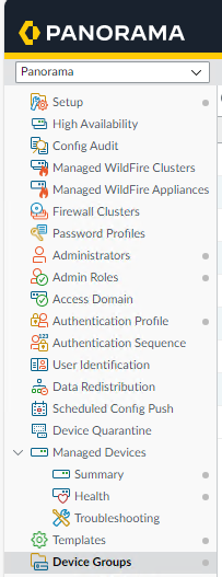
From here you will need to navigate to Device Groups. See Figure 5 below.
Figure 5. Panorama Side Nav
Now, we will create a New Device Group for the sites' data firewall to be managed:
Select Add at the bottom.
In the Name Field Enter the Site Name in the Name Field (Eg. E02)
In the Parent Device Group Field Select Angel BDR FWs
You will need to log in to Panorama, and from there, we will add the firewall as a managed device. Panorama is housed in the US-EAST Region and can be accessed via this link Panorama
Once you log in to Panorama, you will navigate to the Panorama tab in the top Navigation bar. See Figure 6 below for reference.
Figure 6. Panorama Top Nav
From here you will need to navigate to Managed Devices / Summary. See Figure 7 below.
Figure 7. Panorama Side Nav
Now, we will add the firewall to be managed. Please login to the Firewall, and on the Dashboard page, the serial number will be listed. Take note of this for the Add Device dialog in Panorama.
Note
There is a SOP in case the serial number doesn't show up. This seems to be rare, but if it does happen the SOP will be helpful.
At the bottom, select the add button. We will need the serial number of the device being added. The Add Device Diaglog will appear. See Figure 8 below.
Figure 8. Panorama Add Device
Here, you will enter the serial number from the earlier. After entering the serial number, select the Generate Auth Key button. This will generate an auth key that will be needed to point the Firewall at Panorama. Please take note of this auth key for a later step.
After Selecting okay the Device Association Screen will appear. From here you will set the following fields:
Device Group: (For FW-001v Select the Site Under Angel BDR FWs)
Template Stack: Select the Name of the Firewall
Auto Push on 1st Connect: Check the box
Now select OK at the bottom.
Info
We need to commit our changes to the Panorama running configuration. Currently, they are only part of the candidate configuration.
In the top right of the screen click on the Commit drop down and select Commit to Panorama. Once the dialog appears Select commit at the bottom.
For this section, you must log in to the Firewall to be pointed at Panorama. Please consult the IP cut-sheet for the deployment.
Login to the Firewall via its IP Address. Once logged in, in the Top Nav Bar, select Device.
Once you are on the Device page, you should see Panorama Settings. Now select the cog wheel to the right of Panorama Settings. This will open the Panorama Settings Dialog.
Now enter the hostname of Panorama under Panorama Servers.
Info
Panorama FQDN: E01-NM-001v.netops.angel.net
Locate the Auth Key we generated in the earlier step and paste or type it into the Auth Key section. Now select OK.
Now select Commit on the top right of the top nav bar. Once the Commit Dialog
Now Navigate back to Panorama and go back to Managed Devices / Summary. In the list Your Firewall should show connected under Device State.
Warning
If your device is not connected, the E01 Data Firewall may be blocking connectivity from your firewall to Panorama. Contact E01 Network Operation for assistance.
Note
At this point, once the device shows "CONNECTED" and the policy/templates are synched, you should be sure your new FW has the latest Software OS. There is a SOP on how to update the Firewall OS that you can follow. Make sure it matches the Panorama Software OS version.
WolfPack provides Intrusion Prevention Services (IPS) to the Enclave. In this section, we will deploy the IPS and cover the associated steps to ensure the manager configures and adopts it properly.
Info
The IPS in WolfPack Only uses in-line pairs (ILP). An ILP is a set of bonded interfaces that act as a bump in the wire. It is transparent to the network and does not require an IP address to inspect traffic. The ILP allows the IPS to take action on the traffic.